
Winson Optics
Numerical Control Processing & Forming
ISO 9001:2015 certified precision manufacturing. We specialize in complex optical geometries, inner cut-outs, and freeform 3D surfaces.
Three Core Forming Processes
Engineers rely on tolerance specs, not marketing adjectives. Each process card below includes verified Technical Limits from our production data.
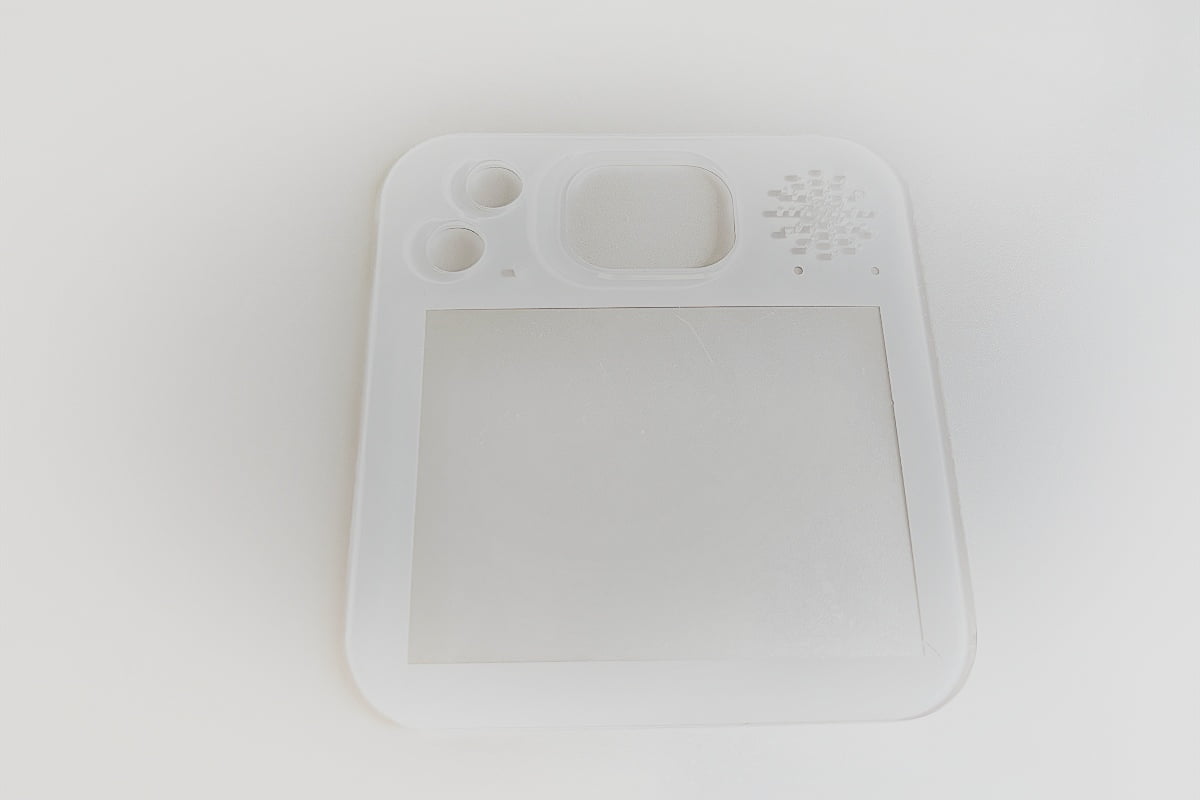
Inner Cut-outs & Drilling
Specialized in micro-holes and complex internal cut-outs for sensors, cameras, and embedded hardware components.
Technical Limits
- Min. Hole Diameter< 0.8 mm
- Positional Tolerance±0.05 mm
- Min. Wall Thickness0.4 mm
- Edge Chipping (Max)≤ 0.03 mm
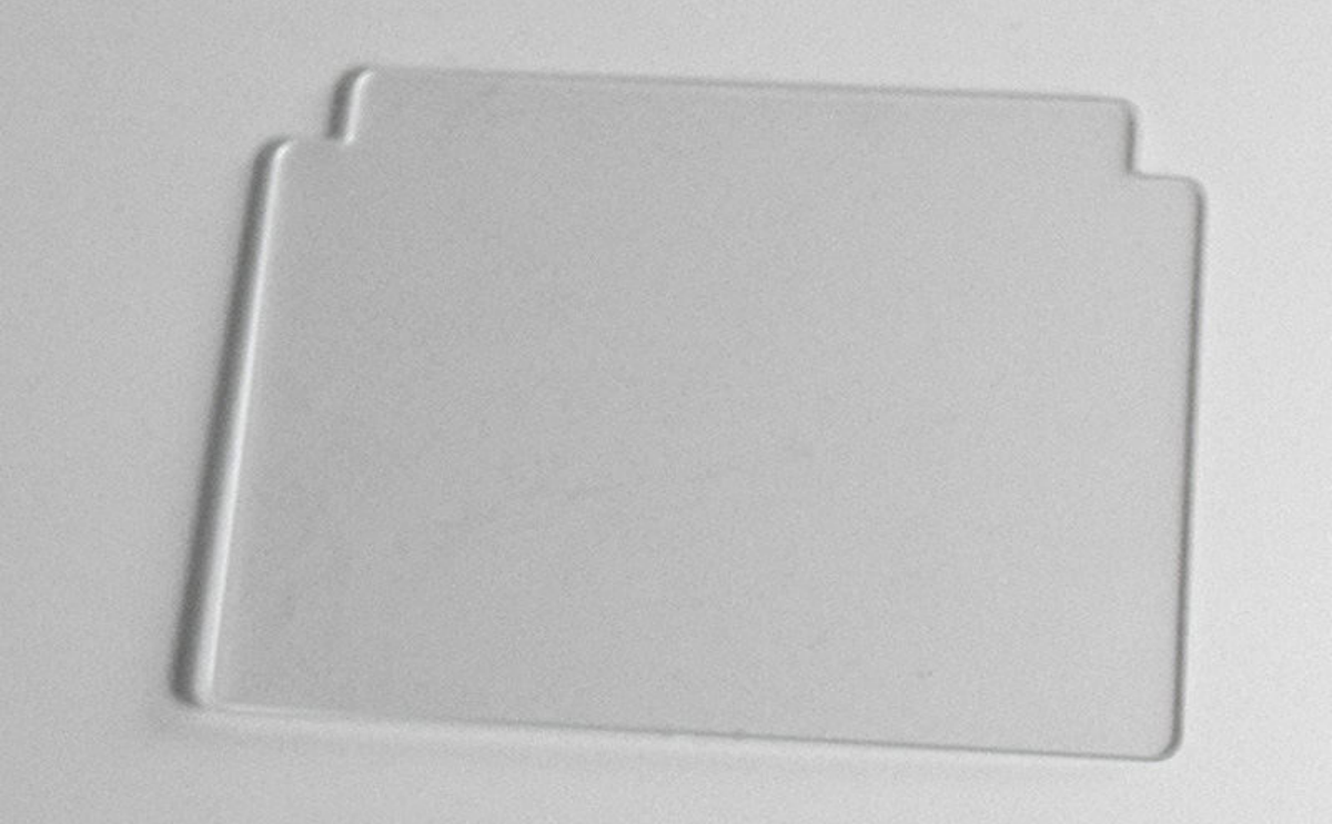
Step Glass Processing
Multi-level CNC steps designed for IP68-rated seamless bonding with magnesium or plastic frames in ruggedized environments.
Technical Limits
- Min. Step Width0.5 mm
- Step Height Tolerance±0.02 mm
- Flatness (Step Face)≤ 0.01 mm
- Max. Step Levels3 Levels
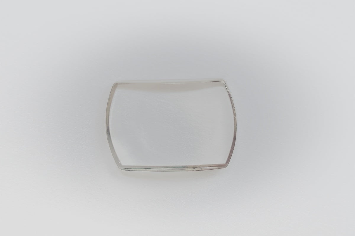
Irregular 3D Contouring
5-axis synchronous grinding for automotive displays and ergonomic wearable glass with compound curvature profiles.
Technical Limits
- Surface Roughness (Ra)< 0.2 μm
- Profile Tolerance±0.03 mm
- Min. Contour RadiusR 0.3 mm
- Axis Synchronization5-Axis CNC
We Solve Design Conflicts Before Mass Production.
"A perfect CAD drawing doesn't always yield a perfect product. We bridge the gap between aesthetics and manufacturability."
Common Yield Killer: Stress Concentration
Sharp internal corners create micro-crack initiation points during thermal cycling, leading to catastrophic yield loss in high-volume production.
Sharp Corner (0° radius)
Stress concentration at corner
R-Angle ≥ 0.2 mm
Stress distributed evenly
* Based on high-alumina glass inner cut-out production batch, n=5,000 pcs.
Winson Optimization: Tool-Path Refinement
By adjusting the feed rate at the exit point, we eliminate the 'chipping' issue common in high-alumina substrates -- verified via 50× micro-scan post-process.

"Iris's team reduced our prototype scrap rate from 22% to 3% through one simple edge modification."
-- Medical Device OEM, GermanyMaterial-Specific Parameter Libraries
Machining difficulty directly correlates with tooling cost and lead time. Use this guide to align material selection with your project budget and schedule.
High-Alumina
Panda / Gorilla / Dragontrail
Difficulty
High hardness requires diamond tooling; edge chipping risk requires controlled feed rates.
Sapphire
Ultrasonic CNC Grinding
Difficulty
Mohs 9 hardness -- the hardest material we machine. Requires specialized diamond wheels.
Optical Plastics
PMMA / PC / Composite
Difficulty
Lower hardness enables faster cycle times; PC requires CNC routing to prevent yellowing.
Custom Substrates
Borosilicate / Quartz
Difficulty
Brittle fracture risk requires slow feed rates and frequent coolant flushing; quartz demands specialized tooling.
Verification Lab: Every Micron Counts
Dimensional Audit
Automated VMS measurement for 100% inspection of critical step dimensions and hole centers. This ensures absolute precision before your components reach the assembly line.
Measurement uncertainty: ±0.01 mm.
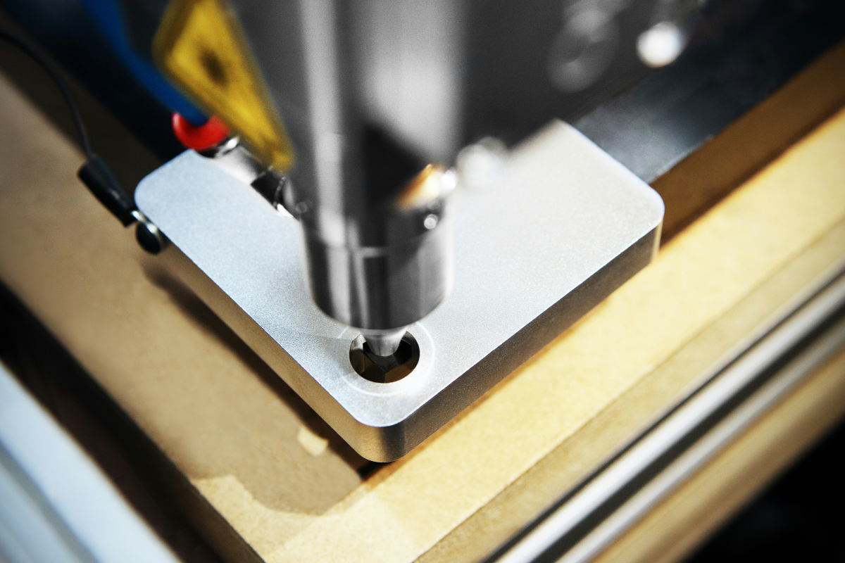

Edge Quality Scan
We perform a 50× micro-scan to ensure zero microscopic chipping. This critical step guarantees long-term structural reliability under thermal stress.
Pass criterion: ≤ 0.03 mm edge breakout.
Surface Tension Test
Post-CNC dyne testing ensures substrate surface energy is perfectly optimized for subsequent coating stacks, preventing peeling or delamination.
Target: ≥ 42 mN/m for AR/AF adhesion.
Ready to optimize your design?
Our engineering team assesses feasibility and responds within 24 hours.